Lanes: Step 3 - Defining Rf Lines
Retardation factors (Rf) are automatically calculated for each detected band. If
no Rf lines are present the Rf values are based on the borders of the image or the
user defined region of interest. Since the image analyzed is a crop from the original
plate there is a need to define Rf lines in order to obtain the correct Rf values.
To define Rf lines expand Editing panel by click on the Editing button
located below the Analysis button in the right part of the window. In the
Editing panel there are several tools to manually fine tune the automatic
analysis results.
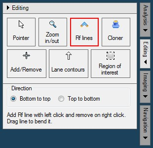
In the Editing panel select the Rf lines ( ) tool, which is used for editing Rf lines. Below all the tools the
properties for currently selected tool is shown. ) tool, which is used for editing Rf lines. Below all the tools the
properties for currently selected tool is shown.
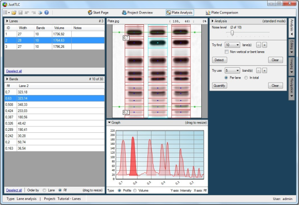
Move the mouse pointer on to the image surface and click in the middle of the second
band from the bottom in lane 2. In the window that appears enter the Rf value 0.2
and click the Ok button. An Rf line is created and all the Rf values are
recalculated. Repeat above steps but click on the second band from the top instead
and enter the Rf value 0.7 instead.
All Rf values have now been updated according to given lines and should look similar
to as shown below.
The TLC plate is now ready for data comparison.
Lane Analysis
Spot Analysis
|